|
|
|
| |
|
Instructions
for
FK 50 (no. 250, 250g)
|
| |
| In order
to enjoy many years of flying with your KAVAN FK 50 engine,
we recommend you to follow the operating instructions carefully.
(read
safety instructions) |
| |
 |
TEST
BENCH |
| |
Mount
the engine on a heavy duty test bench (solid table which
will hold up to the power of this engine; add weight if
necessary). Install a fuel tank (500 ccm/16 oz - No. 31A)
directly behind the engine, at the same height as the
carburetor. Be sure to use an in-line fuel filter (No.
19). Attach a pushrod to the carburetor arm and clamp
it so that constant throttle settings can be maintained.
|
| |
|
|
LUBRICATION |
| |
The
lubrication system of the KAVAN FK 50 is the same as that
used in full scale engines. The inner parts of the engine
are lubricated by an oil pump channeling oil from the
sump to all movable parts. During inverted flight, lubrication
of the connecting rod is assured through the downward
flow of engine oil.
|
| |
|
|
OIL
SUMP |
| |
A
knurled, slotted screw, attached to the dip stick, is
installed in the crankcase behind the left cylinder. Remove
this screw and pour 30 ccm (1 oz) of four-cycle motor
oil into the sump. Using the enclosed injection syringe
will simplify this procedure. While the oil level should
not be lower than indicated on the dip stick (lower mark
on the stick), a maximum amount of 30 ccm (1 oz) should
not be exceeded. When checking the oil first remove the
dip stick, clean it and dip it into the oil completely.
During engine break-in, the oil level must be checked
after using the contents of one fuel tank, or after 15
minutes of operating time.
|
| |
|
|
FUEL |
| |
As
the FK 50 has a separate lubrication system, we recommend
a fuel consisting of high quality, water-free methanol
with 2% oil. During engine break-in (4 to 5 operating
hours) no other oil but degummed AAA castor oil may be
used. To use any other oil but degummed AAA castor oil
(for example synthetic oils) will void the warranty.
After the engine break-in you may use synthetic oils
(high quality only[), also for the oil sump, instead
of castor oil in order to achieve a good mixture. Before
stopping the engine you should run it at full throttle
for at least a minute in order to prevent damage from
corrosion inside the FK 50.
|
| |
|
|
CRANKCASE
VENTILATION |
| |
A
pressure relief valve, for crankcase ventilation, has
been installed in the front part of the crankcase forward
of the front bearing. The white plastic cover, which serves
as protection for the pressure relief valve during transportation
or storage, has to be removed prior to starting the engine.
This pressure relief valve must not be sealed during operation.
Keep the length of the air relief tube (silicone) as short
as possible. Tile diameter of the air relief tube should
be as large as possible - at least 3 mm ('0.1 '~) - so
that the pressure inside the crankcase can escape.
|
| |
|
|
RUNNING-IN
(BREAKING-IN) |
| |
For
long life and high performance the FK 50 requires the
correct breaking-in procedure. All movable parts are manufactured
from wear-resistant, hardened material and need an extended
period of break-in. Not only the compression rings have
to be run-in properly, also the important oil scraper-rings
have to create their own cylinder path with a sealing
effect. For breaking-in the engine, we recommend the propeller
20 x 10" (No. 333,252C). After the engine has been run
in, end while it is still warm, retighten the screws and
nuts on the flanges and crankcase because the screws and
gaskets will be set due to the heat, and thus, the screws
and nuts tend to loosen.
|
| |
|
|
STARTING |
| |
Fill
the fuel line and prime the engine by choking the carburetor
intake with your finger and turning the propeller a few
items towards the left; an engine primer bottle (No. 25)
may be used instead if preferred. Close the carburetor
barrel leaving an opening of approximately 1mm (0.04").
Connect both glow plugs to the battery. When sufficient
fuel has been' pumped into the engine and both glow plugs
are hot, the engine will start immediately after flipping
the propeller a number of times. Gradually apply more
throttle (half throttle) and disconnect the battery after
approximately 15 seconds of operating time. Do not concern
yourself with the idle or full throttle at this time,
but set the carburetor so that the engine will run at
between 5,000 and 6,000 Rpm (during break-in a rich fuel
mixture is preferable to a lean one).
|
| |
|
|
CARBURETOR
SETTING |
| |
A
certain amount of time is required to familiarize yourself
with the functions of this carburetor. It is basically
set and adjusted at the factory. Therefore you only have
to very carefully make fine adjustments at the adjustment
screw (5) (f/4 - f/2 turn: clockwise = leaner, counter.
clockwise = richer). You should never turn the screws
(4a, 5a), since they were already set correctly at the
factory.
After a total running time of 5 to 6 tanks of fuel has
been accumulated, you can gradually set the carburetor
for maximum Rpm. Slowly turn the needle valve to the
right. Before setting the idle speed, mount the propeller
that is intended for later use. Various aspects influence
the choice of propeller size: the size of the airplane,
wing-profile, available space between ground and crankshaft,
as well as altitude. As soon as the oil scraper-rings
have been run-in, the oil consumption of the engine
will reduce drastically.
|
| |
|
| |
|
| |
As
with most carburetors, the air intake is controlled
by a rotary throttle valve. A rotary throttle valve
adjustment screw (1) is used to set the carburetor for
the idle position. This screw should be set in such
a way that the throttle is just closed when set in the
idle position (check by looking through the air intake).
The air flow required in the idle position is then sucked
in through the idle-air-intake or 'air-bleed' hole (2).
The idle air adjustment screw (3) regulates the effective
size of the air-bleed. The basic setting for the air-bleed
adjustment is with the end of the screw halfway across
the air-bleed hole.
The fuel supply of this carburetor, which was specially
designed for the FK 50, is regulated by a curve-control-system.
With the carburetor correctly fine-adjusted and the
glow plugs disconnected, the engine should run at 1,800
Rpm. If the engine will operate only with both glow
plugs connected, the mixture is too rich. For the following
fine-adjustments, please use the long socket head screw
wrench supplied. Loosen the lower clamp screw (4) of
the curve-control-arm (6) (steel spring). For readjusting,
turn only the small idle-adjustment-screw (5):
For leaner fine setting: clockwise.
For
richer fine setting:
counter-clockwise.
These adjustments will cause the lower curve-control-arm
to slide out of, or into, the carburetor body and thereby
reduce, or enrich, the fuel supply. When the desired
idle setting has been reached, tighten the lower clamp
screw (4) to prevent the idle setting from accidentally
being changed. With every idle readjustment on the curve-control-arm,
the needle valve must be reset (leaner or richer, respectively)
|
| |
|
|
OIL
CHANGE |
| |
We
recommend the first oil change after running the engine
for half an hour. Remove the magnet oil drain plug from
the bottom of the sump, using a glow plug wrench, and
let the oil flow out. The magnet portion of the oil drain
plug collects fine metallic particles abraded during the
engine break-in and should be cleaned with cloth material.
After reinstalling the oil drain plug, pour another 30
ccm (1 oz) of multigrade automobile oil into the sump.
After operating the engine, the oil will mix with particles
of soot, of castor oil and condensed water from methanol.
Therefore, we recommend (to prevent damage from corrosion):
1. An oil change after each day of flying with this
engine or, alternatively, after 2 to 3 hours of operating
time. It is better to change the oil while the engine
is still warm.
2. Following every flying session, be sure and let the
engine run at full throttle for at least one minute
so that any water that may have collected in the sump
can evaporate. Then pull the fuel line and let the engine
run out dry.
|
| |
|
|
VALVE
SETTING |
| |
Let
the engine cool down and remove the valve covers (with
inscription 'Continental') which will allow easy access
to the rocker arms. The required valve clearance is between
0.04 mm and 0.10 mm (0.002" and 0.004"). An effort should
be made to achieve the minimum clearance of 0.04 mm (0.002").
With each rotation of the crankshaft, one cycle takes
place alternately in the left and right cylinder. When
turning the engine by hand you will observe which valve
does not move as the piston is at the top of the compression
stroke, i.e. when both valves are closed. Now check this
cylinder using a feeler gauge; the valve clearance can
be corrected with the adjustment screws. Important: Tighten
the lock nut M 3, check the valve clearance again, then
secure the lock nut in place.
|
| |
|
|
MAINTENANCE |
| |
Besides
the oil change, as described above, it is also very important
to check and adjust the valve clearance. The first checkup
and/or adjustment should take place after 2 hours, the
2nd one after 5 hours and further ones after 10 to 15
hours of operation.
|
| |
|
|
DISASSEMBLY |
| |
Only
factory authorized service representatives (see warranty
card) should be entrusted with the disassembly of your
FK 50. Unnecessary dismantling is not recommended for
any type of model engine and should be avoided. If you
like to disassemble your engine by yourself please note
you are doing that at your own risk - to do so will void
any claim for warranty.
|
| |
|
|
NOTE |
| |
Due
to its large displacement, the FK 50 has a strong suction
capability. Make sure that the engine cowl is suitably
vented to allow plenty of air to reach the carburetor
intake, as well as providing a generous through-flow of
air for cooling the engine. Exchange the plugs only by
hand and very carefully in order to avoid a damage of
the thread in the cylinder head.
|
| |
|
|
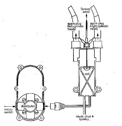
ADDITIONAL
INFORMATION for the FK 50 WITH IGNITION (No. 250G) |
| |
The
KAVAN FK 50 engine with integrated spark-ignition system
offers many advantages in operation, including easier
starting, reliable idle, higher Rpm and reduced fuel consumption.
The micro switch (No. 278), which is mounted on the carburetor,
retards the spark (for starting and idling) and advances
it for full power.
The ignition system employs a Hall Effect (magnetic)
pickup (no points to burn, oil-up or get out of adjustment)
and solid state components throughout and is very reliable.
We recommend the continued use of methanol/castor fuel
(as specified in the instructions) rather than a gasoline-based
fuel. It is cooler running, safer and gives more power
and greater reliability.
1. The ignition coil (which also incorporates the electronics)
must be installed on the left side of the engine (when
viewed from the front) since the screened spark plug
leads are of appropriately different lengths. The three-core
(red/blue/black) lead from the coil must be plugged
into the four-pin left socket of the distributor (again
viewed from the front). The similar (red/blue/black)
lead from the micro switch must be plugged into the
right socket of the distributor. Please note that the
leads should be routed so that they cannot come into
contact with the exhaust pipe, otherwise
insulation will be damaged - which will cause a short-circuit.
From time to time, the spark plugs should be checked
and, if necessary, adjusted to a gap of 0.2 - 0.3 mm
2. Ground (earth) the brown wire to one of the upper
screw-5 of the intake manifold.
3. A 4.8 volt 500 ma NiCd battery pack (sufficient for
approximately 1 hour of running between charges) or
4.8 volt 1,200 ma (approximately 2 hours) is required.
This is not furnished with the engine and can be obtained
from your local hobby shop. The battery should be connected
to the two-core (black/red) lead from the coil via a
regular slide switch.
|
| |
|
| |
Remember:
red wire to battery positive (+)
black wire to battery negative (')m
Warning: If you mix up the wiring, the electronics will
be destroyed.
Note: The ignition system must be operated from its
own, separate NiCd battery; do NOT connect it to the
receiver battery! it is also advisable to keep the RC
components (receiver, servos, battery, slide switch
and wiring) as far away as possible from the ignition
system.
4. Recheck all connections before applying power to
the system - as already explained, an incorrect hookup
will result in damage to the system.
5. The spark timing is factory-set before delivery.
However, it may be adjusted as follows: Start the engine
and let it run for approximately 5 minutes (engine must
be warm for correct setting). You are behind the engine.
While it is running, the timing can be adjusted by rotating
the distributor a few degrees with the 3 mm (0.12'~
dia. steel rod supplied. Counter-clockwise movement
0.e. to the left - against the direction of propeller
rotation) advances the spark; clockwise (to the right)
retards it. It is not necessary to loosen the distributor
retaining screws; the distributor will turn with steady
pressure on the steel rod (an internal O-ring and sealing
washers prevent accidental movement).
Adjusting the timing is simply a matter of advancing
the spark to produce the highest full-throttle Rpm.
Having adjusted the needle valve to its optimum setting,
slowly turn the distributor against the direction of
propeller rotation no further increase in Rpm is obtained,
then turn it slowly back towards the "retard" position,
but not so far as to cause Rpm to fall. This is the
best running position. Experience has indicated that,
at this position, the engine fires when the piston is
approximately 1.5 - 2 mm (0.06 - 0.08") before top dead
center. Please note that the engine revolutions at which
the micro switch changes from advance to retard (and
vice-versa) should be approximately 2,000 Rpm.
|
|
| |
|
|
|
|
|
|
|
|
|
|
| |
©2004-1998
Model Engine Corporation of America, All rights reserved.
No
part may be reproduced without written permission from
MECOA -- P.O. Box 98 -- Sierra Madre, CA 91025 U.S.A.
|
|

.pg.jpg)