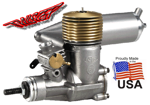
|
|
| |

Part
No. 6170 - K&B .61 R/C
|
|
SPECIFICATIONS
|
|
Displacement
|
.61
Cu. In. (10cc)
|
|
Bore
|
.940
(23.88mm)
|
|
Stroke
|
.880
(22.35mm)
|
|
Compression
|
7.5
: 1
|
|
R.P.M.
|
2,200
- 14,000
|
|
POWER
OUTPUT
|
1.8
HP @ 14,000
|
|
Engine
Weight
|
14.25
Oz. (404g)
|
|
Engine
Weight
|
3.7
Oz. (105g)
|
|
|
| |
|
WARNING
|
|
PLEASE
READ ALL SAFETY
INSTRUCTIONS! Failure to read, understand and follow
these instructions could result in personal injury and/or
property damage to yourself or others.
Take
a few moments to familiarize yourself with the various parts
of the engine. DO NOT DISASSEMBLE YOUR ENGINE! Doing so will
void your warranty. No exceptions!
|
| - |
|
STARTING
AND BREAK-IN
|
|
All
K&B engines are produced to the highest standards and
inspected before leaving the factory, but they are not BROKEN-IN
and will require approximately 60 minutes running before the
full potential of the engine is realized. Break-in can be
accomplished by airborne or bench running.
A
model engine makes sounds that will tell you how its
performing. Youll have to listen very carefully for
them, recognize their message, and make adjustments to the
fuel control needle valves accordingly. The mixture of fuel
and air is controlled by the amount of fuel metered by the
needle valve.
RICH
MIXTURE running is characterized by a slower, sometimes
irregular, sputtering exhaust sound. The exhaust gas will
be smokey and probably contain small droplets of oil. This
condition is good for Break-in since the engine receives excess
lubrication and runs cooler.
FOUR
CYCLING is a rich type setting, but it is fast enough
to pull the airplane. This is the setting you normally look
for before launching the airplane because the engine will
run leaner when airborne.
PEAKED
OR TWO CYCLE. As the main needle is closed (clockwise),
it reduces the amount of fuel mixed with the air drawn into
the engine. At a specific point, which varies with each engine,
air temperature, altitude and relative humidity, the exhaust
note will change quickly into a smooth, powerful note. If
the needle is closed further, the note will stay smooth, but
will weaken. The peak occurs just at the break point from
a rich setting and further leaning will ruin the engine. A
lean setting raises the engine heat above the safe point,
reduces lubrication, and destroys glow plugs due to high combustion
temperature.
This
is very harmful to the engine and your investment. Learn to
tune the engine before flying. Remember, a little rich is
always preferred for long motor life.
|
| |
|
STARTING
PREPARATIONS
|
| Use a Standard
(K&B #7311) or R/C IDLE BAR (K&B #4520) GLOW PLUG, 1.5
volt battery, quality propeller (refer to prop chart below)
and good commercial grade two cycle glow fuel (K&B 100)
with 5% nitro-methane (more helps in cold weather). Be sure
the fuel contains the right percentage of oil (18-22% by volume)
and the fuels oil contains at least a 50-50 mix of castor oil.
Not all synthetic oil. Buy only fuel that lists percentages
on the label by volume. Keep fuel clean and filter it during
fueling. Keep exposure to air to a minimum as methanol will
absorb moisture rapidly. |
| |
|
FUEL
SPECIFICATIONS
|
|
BREAK-IN
FORMULA: 22% Degummed castor oil, 5 to 10% nitro-methane,
and the balance methanol.
AFTER
BREAK-IN: The nitro-methane percentage may be increased
to 15% if desired. LOW QUALITY FUELS
CAN RUIN THE ENGINE IN A SHORT PERIOD OF TIME. Never
use fuel with less than 18% oil content by volume.
|
| - |
|
PROPELLER
SIZES
|
|
Note engine
shaft size 1/4"x28. Be sure prop is balanced.
|
Break-in
|
12x7
|
|
Normal Models
|
12x8
13x6
|
|
| |
|
CARBURETOR
SET UP
|
The
carburetor enables easy adjustment of the idle speed, idle
and high speed mixture.
1.
High Speed Needle Valve
Install
the Remote Needle Valve assembly using the bracket provided.
This may typically be attached to the firewall, cowl or
rear engine mount lug area. The main needle assembly must
be in the fuel line between the tank and the carburetor.
This line should not exceed five (5) inches in total length.
Either nipple on the remote needle may be used for inlet
or outlet.
2.
High Speed-Needle Valve Adjustment
The
needle, located on the Remote Needle Valve Assembly, controls
all the fuel supply to the engine at the maximum throttle
setting. It does not control the fuel at lower throttle
settings.
As
a starting point for the High Speed Needle adjustment, close
the needle valve (clockwise), then open it (counterclockwise)
3 1/2 turns. This setting is an average and will require
further adjustments.
3.
LOW SPEED and MID-RANGE ADJUSTMENT
The
low speed rich/lean adjustment is controlled by the brass
disk located on the side of the carburetor. Using an allen
wrench turn the disc clockwise to lean the mixture
and counter clockwise to richen the mixture.
The rich / lean mixture control is set at the factory and
may require only a fine adjustment for your application.
Normally the maximum adjustment range is only 5 degrees
in either direction.
|
| |
|
ACTUAL
STARTING
|
|
WITHOUT
battery connected, open the carburetor barrel to wide open
position. Open the high speed needle valve as described above.
Choke the engine by placing your finger over the carburetor
air inlet and slowly turn the prop over three times counter
clockwise. You should see fuel being drawn up the fuel line.
If fuel is not drawn into the carburetor, open the main needle
one more turn, and be sure the idle mixture disc notch is
in the upright position, then repeat the above. Fuel should
be drawn into carburetor.
Close
the barrel to about the 1/3 open position and connect the
1.5 volt battery to the glow plug, start the engine with your
chicken stick or electric starter. Once the engine starts,
open the carburetor to full throttle. At this time the engine
should be running very rich. Slowly turn the main needle valve
in and the engine should start speeding up. If it slows, dies
or only starts with a brief bust of power and stops, the needle
valve setting is too lean. Unscrew the needle 1 more turn
and try again. If engine starts, runs slowly and briefly the
mixture is too rich. Turn the main needle in 1/2 turn and
restart. IF THE ENGINE DOES NOT FIRE AT ALL, refer to the
TROUBLE SHOOTING section
in this text.
Now adjust
the main needle as described in STARTING
AND BREAK IN above.
|
| |
|
ADJUSTING
THE R/C CARBURETOR
|
|
K&B
engines are fitted with a variable mixture carburetor which
automatically alters both fuel and air mixtures as its
closed. Best and most reliable carburetor settings are obtained
after engine break-in.
1.
Start the engine and open the carburetor to the full open
position, then adjust for peak R.P.M. with the main needle
as previously described.
2.
Close the carburetor barrel slowly until the lowest possible
speed is reached without the engine stopping.
3.
Go to full throttle after about 10 seconds of idling. If the
engine gains speed slowly, the idle mixture is too rich. If
the engine stops, the idle mixture is too lean. Turn the idle
disc clockwise if mixture is too rich and counterclockwise
if too lean.
The
engine will accelerate from idle to full throttle smoothly
and instantaneously when properly adjusted. The engine may
not idle well at a low setting or accelerate as quickly until
it is well broken in.
|
| - |
|
|
|
1.
BREAK-IN running should be done with the recommended
propeller at a slightly rich setting. The needle valve
should be set at a point just into this range from a four
cycle setting. Fly the plane at maximum throttle for 2 minutes,
then throttle back for approximately 30 seconds. Repeat this
sequence until approximately 45 minutes of accumulated running
time has been obtained. Additionally, certain maneuvers, such
as CUBAN EIGHTS, that allow the engine to
load and unload are recommended. AVOID PROLONGED CLIMBING
MANEUVERS AT MAXIMUM THROTTLE.
2.
After the first 45 minutes change to normal size prop and
fly an additional 45 minutes. Continue to run the engine at
a slightly rich four cycle setting and fly your normal pattern.
3.
After the above break-in period, run the engine at a normal
peak needle valve setting. This should be a little on the
rich side because engines run leaner in the air. 5% - 15%
nitro may be used.
|
| |
|
BENCH
BREAK-IN
|
|
NOTE
THAT THE ENGINE MUST BE FIRMLY MOUNTED ON A SOLID TEST STAND.
DO NOT CLAMP ENGINE IN A VISE. Muffler may be used during
bench break-in.
The initial
bench break-in period is also approximately 90 minutes (20
to 30 minutes bench and 60 minutes airborne). During this
time, use the recommended break-in propeller and run the engine
at a rich setting. It is best to run the engine for about
10 minutes, then allow it to cool. The heating and cooling
aid break-in.
1.
Start the engine and run it at a rich full throttle for about
1-1/2 minutes, then let it fast idle (about 3500 rpms)
for 30 seconds. Repeat this sequence for about 20 minutes
of running time.
2.
Increase the full open throttle time to about 3 minutes followed
by a 30 second idling period. Do this for an additional for
20 minutes.
3.
Install the engine in your aircraft. Using an normal size
prop, proceed as described in step 2 of AIRBORNE
BREAK-IN.
|
| - |
|
AIRCRAFT
INSTALLATION
|
|
These
engines are designed for beam type mounting. Securely mount
the engine an hardwood mounts or firewall mount with a good
quality motor mount. Be sure mounting surface is flat and
parallel and all mounting holes line up, the crankcase could
become distorted if screws or mounts are forced. We strongly
advise against using a soft or rubber mount installation as
our engines are correctly balanced and these mounts can cause
excess vibrations from resonance frequencies. Do not use a
back cover mounting plate as the screw bosses are not designed
to take engine torque.
Fuel
tank should be located as close to the engine as possible.
The center line of the tank should be within 1/2 inch above
or below the center of the carburetor. See illustration.
Muffler
pressure is recommended as it provides an even run throughout
the whole tank of fuel.
|
| - |
|
TROUBLE
SHOOTING
|
|
Generally
most engine starting problems can be traced to bad glow plugs,
weak starting batteries, or inadequate fuel systems.
GLOW
PLUGS: The
glow plug when connected to a 1.5 volt battery should glow
a bright orange. If the plug slightly glows the battery or
plug should be replaced.
If the
seal leaks around the center plug post, replace it.
The glow
plug element should be examined after several flights. If
the element is deformed or touching the side of the plug body,
replace it. If the glow plug element is pitted or has a frosty
look, the engine is running too lean and continued running
will seriously harm the engine.
FUEL
SYSTEMS:
The most frequent problems encountered with fuel systems are:
1.
Improper fuel tank location. The center line of the carburetor
should be located on the center line of the fuel tank.
2.
Fuel pick up in tank is not free.
3.
Dirt or contaminates in the fuel, tank, lines, filter or carburetor.
4.
Holes in the fuel line. The tear resistance of silicon tubing
is very low and its not uncommon to develop a hole where
the fuel line is assembled over the edges of brass tubing.
If the engine runs well on the first half of tank and then
quits, its almost always caused by a hole in the pick
up line inside the tank. Look for bubbles in the fuel line,
this is also a sign of holes.
|
| |
|
MAINTENANCE
|
|
When
you are finished flying for the day, run your engine dry by
removing the fuel line at a moderate speed or allow the fuel
tank to run dry. It is best to squirt some K&B AFTER RUN
OIL in the carburetor, then flip the propeller about 10 to
20 times. This oil will keep castor based fuels from gumming
and protect internal engine parts from rust and corrosion.
When storing your model between flying sessions, it is best
to wrap your engine in a rag or plastic to prevent dust, dirt
and moisture from entering the engine. The engine should also
be wrapped in a rag at the flying field between flights.
If dirt
does enter the engine do not turn it over until it has been
flushed out completely. Alcohol is recommended for this. DO
NOT USE carburetor cleaner or chlorinated industrial solvents
as they may attack the plastic parts of the engine. The following
steps may be used as a disassembly/assemble guide:
1.
Remove carburetor, muffler and glow plug.
2. Remove the back cover and head.
3. Flush engine out completely using alcohol
or mild solvent.
4. Install back cover and head.
5. Install the glow plug and carburetor.
SCREW
ON HEAD: The screw on head on your new 61 ABC engine has
been torqued to 26 foot pounds at the factory. After you have
run 2 to 3 gallons of fuel through the engine, check the head
for tightness with the spanner wrench supplied. Check the
head immediately after a flight so the engine will be at running
temperature. Support your engine by firmly holding the prop
and front of the engine so as to not break engine mount loose
from the fire wall. NOTE: The head is installed at the factory
with anti-seize compound. Before reinstalling head, make sure
threads are clean and reapply anti-seize compound for aluminum
(available at auto parts stores) to threads.
|
| |
|
|
|
|
|
|
|
|
©2004-1998
Model Engine Corporation of America, All rights reserved.
K&B and the oval logo are Registered Trademarks of Model Engine
Corp. of America
Registered U.S. Patent Office
No
part may be reproduced without written permission from
MECOA/K&B -- P.O. Box 98 -- Sierra Madre, CA 91025 U.S.A.
|
|